What's good Ampgarage?
Lately decided to mod a 102 style (not really but sort of) OTS to 124 specs. And decided to purchase some more Orange 6ps caps (3 Orange Drops where the 715p type and that is so not on).
In the mean time I looked into the whole outside foil thing. And decided to do it the right way all together. I came across the following statement on aikenamps.com.
"The proper way to connect the outside foil is to the low impedance side of the circuit, which, in the case of coupling caps, will normally be the plate of the previous stage. If it is a bypass cap to ground, connect the outside foil to the grounded side. If it is a bypass cap from a signal to B+, connect the outside foil to B+. The outside foil will act as a shield against electric field coupling into the capacitor, so you want it to have the lowest impedance return path to ground". http://www.aikenamps.com/index.php/wher ... capacitors
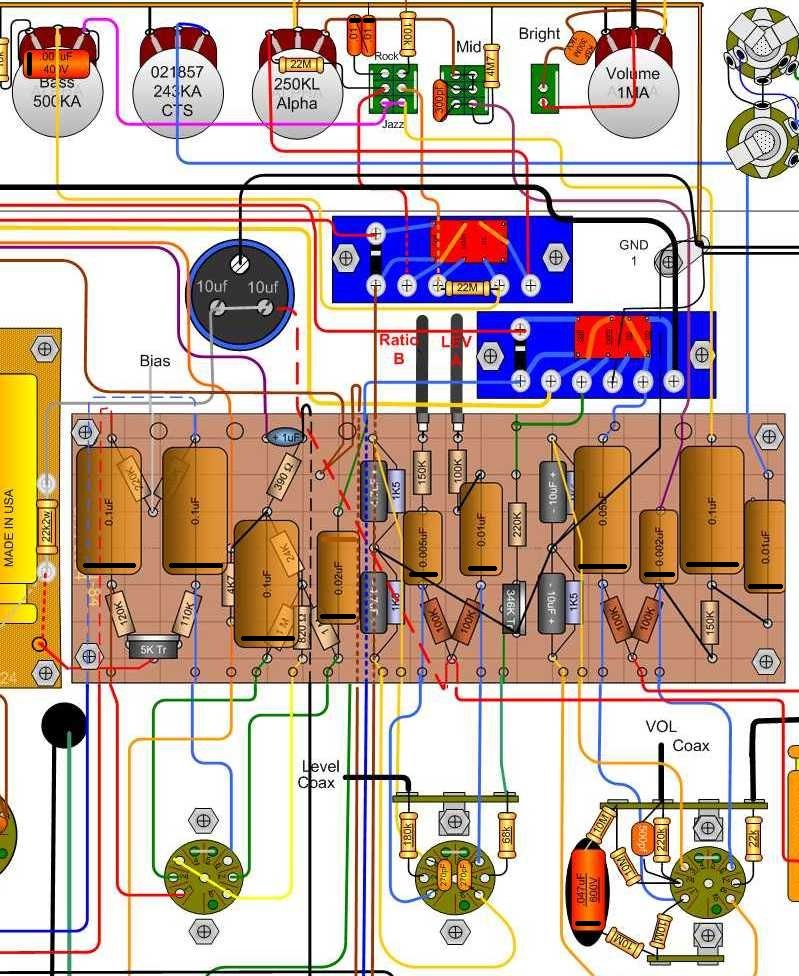
Which led me to the following Outside foil positions. The black lines are the outside foil markings. (I felt free too borrow and modify it from the allready existing 124 Lay-Out. Hopefully that's ok?)
[img:799:976]http://i932.photobucket.com/albums/ad16 ... erFoil.jpg[/img]
Reasons:
1. Orange Drops (OD's) outer foils on the potentiometers headed towards the ground.
2. OD's outer foil on V1LNFB headed toward Anode since the grid is more sensitive?
3. Practically all the OD's outer foils on the circuit bord headed towards the Anode's (or B+) I also saw that on most of the Two Rock gutshots I examined. Particulary around v1 and the PI.
4. I am not sure about the 0.02 and 0.1 cap towards the grids of v3.
Could anyone shed some light on the matter? Am I thinking correctly or have I made some mistakes?
Capacitor Outside Foil Placement Dumble
Moderators: pompeiisneaks, Colossal
-
martin manning

- Posts: 13356
- Joined: Sun Jul 06, 2008 12:43 am
- Location: 39°06' N 84°30' W
Re: Capacitor Outside Foil Placement Dumble
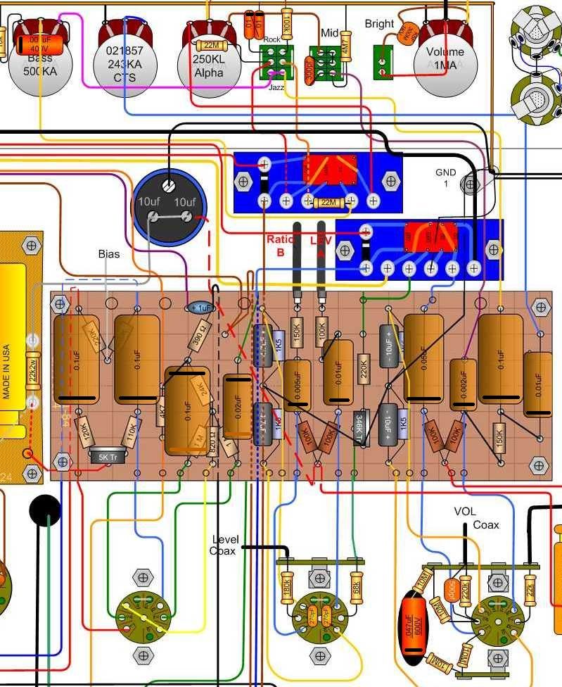
Sounds good except flip the *third* cap from the left in your marked-up layout.
Last edited by martin manning on Sun Apr 20, 2014 12:40 pm, edited 1 time in total.
Re: Capacitor Outside Foil Placement Dumble
Updated.
[img:799:976]http://i932.photobucket.com/albums/ad16 ... Foil-1.jpg[/img]
Why exactly? I can't figure out which connection is the more sensitive part (or high impedance for that matter).. the grids of v3? Or the green wire coming from FX loop return.
[img:799:976]http://i932.photobucket.com/albums/ad16 ... Foil-1.jpg[/img]
Why exactly? I can't figure out which connection is the more sensitive part (or high impedance for that matter).. the grids of v3? Or the green wire coming from FX loop return.
-
martin manning
- Posts: 13356
- Joined: Sun Jul 06, 2008 12:43 am
- Location: 39°06' N 84°30' W
Re: Capacitor Outside Foil Placement Dumble
Sorry, third cap from the left. Outside foil away from the PI grids.
Re: Capacitor Outside Foil Placement Dumble
Haha ok, you were also counting the cap across the basspot?
Update:
[img:799:976]http://i932.photobucket.com/albums/ad16 ... Foil-2.jpg[/img]
Update:
[img:799:976]http://i932.photobucket.com/albums/ad16 ... Foil-2.jpg[/img]
-
martin manning
- Posts: 13356
- Joined: Sun Jul 06, 2008 12:43 am
- Location: 39°06' N 84°30' W
Re: Capacitor Outside Foil Placement Dumble
No I just counted wrong :^\
-
titser_marco
- Posts: 131
- Joined: Tue Mar 13, 2007 3:08 pm
Re: Capacitor Outside Foil Placement Dumble
Hi! Sorry, noob question: how do you identify the outside foil side on a Sprague orange cap? 
Re: Capacitor Outside Foil Placement Dumble
Simplest way is with an oscilloscope. Set the volts/div to the minimum setting and the time base around 20 ms.
Connect the scope probe and ground clip to the cap leads and pinch the cap body between your fingers. Swap the leads and repeat. The lowest amplitude on the scope will have the outer foil connected to the ground lead on the scope.
Connect the scope probe and ground clip to the cap leads and pinch the cap body between your fingers. Swap the leads and repeat. The lowest amplitude on the scope will have the outer foil connected to the ground lead on the scope.
Re: Capacitor Outside Foil Placement Dumble
If you don't have a scope check this thread out;
http://ampgarage.com/forum/viewtopic.ph ... l+test+box
I built the switch box years ago , works great, I use it everytime I build an amp.
http://ampgarage.com/forum/viewtopic.ph ... l+test+box
I built the switch box years ago , works great, I use it everytime I build an amp.
-
glasman

- Posts: 1446
- Joined: Wed Jan 19, 2005 10:37 pm
- Location: Afton, MN (St Croix River Valley)
- Contact:
Re: Capacitor Outside Foil Placement Dumble
Same procedure I use. Kind of a pain if you are testing say 100 or 200 caps, but worth it in the end.John_P_WI wrote:Simplest way is with an oscilloscope. Set the volts/div to the minimum setting and the time base around 20 ms.
Connect the scope probe and ground clip to the cap leads and pinch the cap body between your fingers. Swap the leads and repeat. The lowest amplitude on the scope will have the outer foil connected to the ground lead on the scope.
O-Scope is the best method, harder to see on a .001 or .002, but it is still visible. If you are having troubles seeing the difference, try setting the cap near an AC power cable or hold the cord of an ac power cable in one hand and the cap in the other. That will usually bring the signal (50 or 60hz) up quite a bit.
Gary
Located in the St Croix River Valley- Afton, MN
About 5 miles south of I-94
aka K0GWA, K0 Glas Werks Amplification
www.glaswerks.com
About 5 miles south of I-94
aka K0GWA, K0 Glas Werks Amplification
www.glaswerks.com
-
Smokebreak
- Posts: 1391
- Joined: Tue Dec 18, 2012 5:53 pm
- Location: Texas
Re: Capacitor Outside Foil Placement Dumble
Came across this a while ago ...
https://youtu.be/1f-LdpJiAk4
https://youtu.be/1f-LdpJiAk4
Re: Capacitor Outside Foil Placement Dumble
there is a somewhat lengthy thread here about finding cap orientation along with photos & youtube references
http://el34world.com/Forum/index.php?topic=11427.0
With respect, 10thtx
http://el34world.com/Forum/index.php?topic=11427.0
With respect, 10thtx

-
norburybrook

- Posts: 3290
- Joined: Mon Jan 06, 2014 12:47 am
- Location: London
- Contact:
Re: Capacitor Outside Foil Placement Dumble
OK, I'll bite...... what's the difference in tone doing this?
I haven't done this in either of my dumble type builds.
What am I missing?
Marcus
I haven't done this in either of my dumble type builds.
What am I missing?
Marcus
-
martin manning
- Posts: 13356
- Joined: Sun Jul 06, 2008 12:43 am
- Location: 39°06' N 84°30' W
Re: Capacitor Outside Foil Placement Dumble
The benefit is possibly a bit lower noise floor. The theory is that the lead connected to the outer foil should be shown the lowest possible impedance to ground to minimize any noise voltage developed there due to stray EMF.