Hey Wreck fans... Some more interesting technical data thanks to the digital wizardry of Tim Hulsey. We worked hard over the weekend to get the drawings right.
This data is based on actual Rocket amps, so no need to ask if we're sure... it's based on the real deal.......
Tim is a master at this stuff, I must give much credit to his mad drawing skills!!!
EDIT: Updated version uploaded with corrections on the Bass pot 11 June 08
EDIT: Layout updated with corrected rectifier pin numbers 12 June 08
EDIT: Schematic updated, removed extra fuse on 120VAC supply 13 June 08
EDIT: BOM updated with correct Panasonic part #s, other small stuff 21 July 08
Edit: BOM Rev 1.4 posted- numerous cleanup items
EDIT" New Layout with clearer text on the Screen Resistors
EDIT 21 Sept 08- Updated BOM.
EDIT 1 Nov 08 BOM Updated
EDIT: 23 Nov 08- Major BOM Revision, Revised Voltage Chart
EDIT: New Layout posted with corrected cap stack ground wires
EDIT: 19 Jan 00- updated BOM, little stuff.
EDIT: 09 Mar 09- changed B+ wire on Rectifier tube
NOTE: The Rocket layout shows 100K Bleeder resistors in the drawing, but note that they are NOT in an original Rocket- there's a small note stating this, but it's not very obvious.
Ron Worley and Tim Hulsey (DrHulsey)
EDIT: 29 Oct 09- BOM updated
EDIT: 23 Nov 09- BOM updated
Rocket Documents
Moderators: pompeiisneaks, Colossal
-
Ron Worley

- Posts: 908
- Joined: Mon Dec 24, 2007 8:21 pm
- Location: Keller, TX
1 others liked this
Rocket Documents
You do not have the required permissions to view the files attached to this post.
Last edited by Ron Worley on Mon Nov 23, 2009 11:59 pm, edited 24 times in total.
Ron

-
Fischerman
- Posts: 819
- Joined: Thu Dec 07, 2006 3:47 pm
- Location: Georgia
Re: Rocket Documents
Very nice! I think the bass control ground wire is on the wrong lug in the layout. The right lug should be grounded...the way it is now the entire 'bass end' of the tone stack is always grounded.
-
Ron Worley
- Posts: 908
- Joined: Mon Dec 24, 2007 8:21 pm
- Location: Keller, TX
Re: Rocket Documents
Fisch-
Great eyes, thanks for the catch.... after awhile it starts to blur....
EDIT: 19 Jan 09- Rocket Voltage chart added
Ron
Great eyes, thanks for the catch.... after awhile it starts to blur....
EDIT: 19 Jan 09- Rocket Voltage chart added
Ron
You do not have the required permissions to view the files attached to this post.
Last edited by Ron Worley on Tue Jan 20, 2009 12:56 am, edited 1 time in total.
Ron
-
Lonely Raven

- Posts: 878
- Joined: Fri Nov 16, 2007 4:09 am
- Location: Bolingbrook, IL
- Contact:
Re: Rocket Documents
Thank you guys so much for this! It's been great being a small part of this Rocket project!
Jack of all Trades,
Master of None
Master of None
Re: Rocket Documents
Is it correct now?Fischerman wrote:Very nice! I think the bass control ground wire is on the wrong lug in the layout. The right lug should be grounded...the way it is now the entire 'bass end' of the tone stack is always grounded.
The #1 or left hand lug goes to ground on the bass pot?
Tom
Don't let that smoke out!
Don't let that smoke out!
-
Fischerman
- Posts: 819
- Joined: Thu Dec 07, 2006 3:47 pm
- Location: Georgia
Re: Rocket Documents
Looking at the back of the bass pot...the two wires from the two caps go to the left lug and the middle lug. The wire from the treble pot goes to the left lug. The 10k resistor goes from the middle lug to ground. The right lug goes straight to ground.
The schematic (IMO) should show that when the wiper on the bass pot is at the 'top' that's the '0' setting and when the wiper is at the 'bottom' then that is the bass on '10' setting. It's just the opposite of the Treble pot and the Volume pot (and the way most pots show on a schematic).
The schematic (IMO) should show that when the wiper on the bass pot is at the 'top' that's the '0' setting and when the wiper is at the 'bottom' then that is the bass on '10' setting. It's just the opposite of the Treble pot and the Volume pot (and the way most pots show on a schematic).
-
pureoldsound
- Posts: 140
- Joined: Sun Sep 10, 2006 7:49 pm
Re: Rocket Documents
Change the 1k 5W screen resistors to 100 ohms...on the schematic
bass ground fix
http://s260.photobucket.com/albums/ii9/ ... detail.jpg
[IMG:302:148]http://i260.photobucket.com/albums/ii9/ ... detail.jpg[/img]
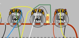
Ok - so is this corrected. I took the liberty of re-drawing this detail. Are we good on this as is.
best ange
[IMG:302:148]http://i260.photobucket.com/albums/ii9/ ... detail.jpg[/img]
Ok - so is this corrected. I took the liberty of re-drawing this detail. Are we good on this as is.
best ange
-
Fischerman
- Posts: 819
- Joined: Thu Dec 07, 2006 3:47 pm
- Location: Georgia
Re: Rocket Documents
No ange, that's the same as it was unless I'm missing something. The green wire doesn't go from the left lug to ground...it goes from the right lug to ground. It appears you just moved the actual solder point of the green wire up the ground buss a little (which does nothing).
-
Fischerman
- Posts: 819
- Joined: Thu Dec 07, 2006 3:47 pm
- Location: Georgia
Re: Rocket Documents
Also, are the bass/treble pot supposed to be audio taper? I thought they were both linear taper. FWIW, I used linear for the treble and audio for the bass and the sweep is very good.
-
Ron Worley
- Posts: 908
- Joined: Mon Dec 24, 2007 8:21 pm
- Location: Keller, TX
Re: Rocket Documents
I will have Dr Hulsey modify the original document, then will post.
The Bass and Treble post were listed as Audio taper in the Matt Taylor schematic, so, that's how we did the layout. I have seen no documentation to the contrary, but would like to see it if we've got it wrong.
Let me know if you find any other errors!
Ron
The Bass and Treble post were listed as Audio taper in the Matt Taylor schematic, so, that's how we did the layout. I have seen no documentation to the contrary, but would like to see it if we've got it wrong.
Let me know if you find any other errors!
Ron
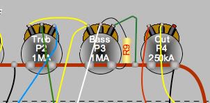
Duh - dislex
man that was helpful - i think this is right now - sorry for the flub
[IMG:302:148]http://i260.photobucket.com/albums/ii9/ ... tail-1.jpg[/img]
[IMG:302:148]http://i260.photobucket.com/albums/ii9/ ... tail-1.jpg[/img]
-
Ron Worley
- Posts: 908
- Joined: Mon Dec 24, 2007 8:21 pm
- Location: Keller, TX
Re: Rocket Documents
You got it right this time!!  Technically, the lug is just bent against the pot casing, which is grounded to the copper wire buss....
Ron
Ron