VVR guidance in Tweed Champ

General discussion area for tube amps.

Moderators: pompeiisneaks, Colossal

bretschwartz
Posts: 17
Joined: Sun Sep 30, 2012 3:01 pm
Location: philly

VVR guidance in Tweed Champ

Post by bretschwartz »

Sorry if this is posted in wrong location.

I just built my first amp... a tweed champ. It works perfect and sounds stunning! Only problem is its too loud to get some crunch.

I just purchased the VVR for cathode amps from Hall amplification and need some guidance on exactly where to install the VVR.

The cathode VVR is supposed to be easier to install but I just don't understand where to make my connections.

Any guidance would be greatly appreciated.

Bret


Image<a href="http://s448.photobucket.com/albums/qq20 ... tailed.jpg" target="_blank"><img src="http://i448.photobucket.com/albums/qq20 ... tailed.jpg" border="0" alt="Photobucket"></a>

Image[/url]
You do not have the required permissions to view the files attached to this post.
bretschwartz
Posts: 17
Joined: Sun Sep 30, 2012 3:01 pm
Location: philly

pics again

Post by bretschwartz »

not sure why image link didn't work, trying again

Image

[/img][IMG:681:553]http://i448.photobucket.com/albums/qq20 ... CBoard.jpg[/img]

Image[/img]
User avatar
xtian
Posts: 7019
Joined: Mon Apr 19, 2010 8:15 pm
Location: NorCal
Contact:

Re: VVR guidance in Tweed Champ

Post by xtian »

Disconnect both red wires from pin 8 of the recto tube and connect them to the B+ Out pad of the VVR. Connect pin 8 of the recto tube to B+ In of the VVR.
markr14850
Posts: 204
Joined: Mon Jun 18, 2007 6:16 pm

Re: VVR guidance in Tweed Champ

Post by markr14850 »

xtian wrote:Disconnect both red wires from pin 8 of the recto tube and connect them to the B+ Out pad of the VVR. Connect pin 8 of the recto tube to B+ In of the VVR.
Wouldn't this put the VVR before the reservoir cap?
User avatar
sliberty
Posts: 1324
Joined: Fri May 26, 2006 5:03 pm

Re: VVR guidance in Tweed Champ

Post by sliberty »

Normally you would put the board in between the first filter and the plates (OT). But since a PCB was used and the first filter is on the board this would require lifting the positive side of the first filter from the board and connecting to this now loose end.

Lift the two red wires from rectifier pin 8.
Lift the positive end of the 22uF cap off of the PCB. Make a small loop with this loose end to connect a new wire through.
Run a new red wire from rectifier pin 8 to the B+ In on the VVR.
Run a new red wire from rectifier pin 8 to the loop on the positive filter cap lead.
Run a new red wire from the two lifted wires to the B+ Out on the VVR.

A terminal strip might help keep this neater.
bretschwartz
Posts: 17
Joined: Sun Sep 30, 2012 3:01 pm
Location: philly

Re: VVR guidance in Tweed Champ

Post by bretschwartz »

sliberty wrote:Normally you would put the board in between the first filter and the plates (OT). But since a PCB was used and the first filter is on the board this would require lifting the positive side of the first filter from the board and connecting to this now loose end.

Lift the two red wires from rectifier pin 8.
Lift the positive end of the 22uF cap off of the PCB. Make a small loop with this loose end to connect a new wire through.
Run a new red wire from rectifier pin 8 to the B+ In on the VVR.
Run a new red wire from rectifier pin 8 to the loop on the positive filter cap lead.
Run a new red wire from the two lifted wires to the B+ Out on the VVR.

A terminal strip might help keep this neater.
Which Cap do I lift ? There are two 22uF Caps, located at C3 & C4. I think the first one but would like confirmation please??

Thanks for the help, I will keep you posted - Bret
User avatar
sliberty
Posts: 1324
Joined: Fri May 26, 2006 5:03 pm

Re: VVR guidance in Tweed Champ

Post by sliberty »

C3 and C4 are not filter caps. They are cathode bypass caps. The filter caps are C6, C7 and C8.

You lift C6 - the one to the far right in the photo you posted.
bretschwartz
Posts: 17
Joined: Sun Sep 30, 2012 3:01 pm
Location: philly

Re: VVR guidance in Tweed Champ

Post by bretschwartz »

sliberty wrote:C3 and C4 are not filter caps. They are cathode bypass caps. The filter caps are C6, C7 and C8.

You lift C6 - the one to the far right in the photo you posted.
Wow! glad I asked!! ... that would have been be an interesting smoke show.. I think i'me good for now, I even know which is the positive end :)

I'll post results later tonight. appreciate the help! Bret
bretschwartz
Posts: 17
Joined: Sun Sep 30, 2012 3:01 pm
Location: philly

Finished the VVR3 Install! works great..

Post by bretschwartz »

bretschwartz wrote:
sliberty wrote:Normally you would put the board in between the first filter and the plates (OT). But since a PCB was used and the first filter is on the board this would require lifting the positive side of the first filter from the board and connecting to this now loose end.

Lift the two red wires from rectifier pin 8.
Lift the positive end of the 22uF cap off of the PCB. Make a small loop with this loose end to connect a new wire through.
Run a new red wire from rectifier pin 8 to the B+ In on the VVR.
Run a new red wire from rectifier pin 8 to the loop on the positive filter cap lead.
Run a new red wire from the two lifted wires to the B+ Out on the VVR.

A terminal strip might help keep this neater.
Which Cap do I lift ? There are two 22uF Caps, located at C3 & C4. I think the first one but would like confirmation please??

Thanks for the help, I will keep you posted - Bret
Finally got the VVR install completed and it works just great! I'll attach a pic, the pot is bottom next to the rec tube. The champ chassis is really small and seemed like the only good place to mount it. I was a little worried because the VVR3 is just above the transformer and was thinking it might cause some interference being so close. Fortunately it didn't interfere and its quiet as a church mouse. I didn't even experience any of the scratchy volume noise that is described in the VVR3 manual.

Do you guys think that the tubes will wear more quickly if I keep the VVR about 50% clipped all the time?

overall, i'm very pleased with the results...Bret

Image[/img]
User avatar
sliberty
Posts: 1324
Joined: Fri May 26, 2006 5:03 pm

Re: VVR guidance in Tweed Champ

Post by sliberty »

Glad it worked out.

I don't see much risk of premature tube failure.

Enjoy!

Steve
bretschwartz
Posts: 17
Joined: Sun Sep 30, 2012 3:01 pm
Location: philly

Re: VVR guidance in Tweed Champ

Post by bretschwartz »

sliberty wrote:Glad it worked out.

I don't see much risk of premature tube failure.

Enjoy!

Steve
Well the VVR3 continues to perform flawlessly! I am extremely satisfied with its performance. The one caveat is that I have already zapped my self twice reaching around behind the amp, contorting my arm to get to the pot.

The champ tweed chassis is so small, I have decided to swap the fuse and VVR3 locations, this puts the VVR3 right next to the lamp in an easy to adjust situation with the added benefit of not having my fingers and arm go numb :)

Anyone every try jamming with a numb arm?

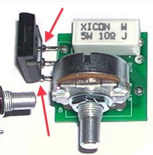
Anyway, my main concern is the 3 pin voltage regulator that will just hang in space inside the chassis. The directions say to heat sink the regulator to the chassis which I can't do because of space constraints.

My thinking is that the champ being only a 5 watt amp won't produce that much heat and the little that it does create would dissipate normally through the voltage regulator.

Is my thinking flawed?

thoughts? concerns?

I attached a pic of the vvr3 with the voltage regulator attached. Mine would be exactly like that, just attached to the board and not the chassis.


thanks for the help.....Bret

Image[IMG:302:306]http://i448.photobucket.com/albums/qq20 ... 9aa79d.jpg[/img]
User avatar
Structo
Posts: 15446
Joined: Wed Oct 17, 2007 1:01 am
Location: Oregon

Re: VVR guidance in Tweed Champ

Post by Structo »

You can use a discrete heat sink on the regulator.

Just go to Mouser or other parts house and look for the right heat sink for that type of package.
Last edited by Structo on Sun Oct 07, 2012 3:49 pm, edited 1 time in total.
Tom

Don't let that smoke out!
tictac
Posts: 610
Joined: Fri Mar 31, 2006 4:42 am

Re: VVR guidance in Tweed Champ

Post by tictac »

You zapped yourself twice :?: :shock:

If that is really true then my belief is that your method of working inside a tube amps is WAY too casual... The first shock should have been enough of a warning but allowing it to happen twice on the same project is bad practise...

Certainly you must be aware that the voltages inside even a little amp like a Champ are... LETHAL!!!! they can KILL YOU!!!! And so fast you'll be dead before you hit the ground...

I'm sure quite a few amp builders on this forum have been shocked; but safe working practises have kept those occurances rare so that we're still alive and able to talk about it...

Please rethink your methods and change them...

TT
User avatar
sliberty
Posts: 1324
Joined: Fri May 26, 2006 5:03 pm

Re: VVR guidance in Tweed Champ

Post by sliberty »

How about a photo of the back of your amp?

As for the regulator, I would leave it attached to the chassis. It needs the chassis to dissipate heat. But, you can run wires from the three pins to your board if you end up moving the board.

But before you move anything, let us see how you have things arranged so far.
User avatar
Structo
Posts: 15446
Joined: Wed Oct 17, 2007 1:01 am
Location: Oregon

Re: VVR guidance in Tweed Champ

Post by Structo »

Taking my idea to a higher level, you could bolt the regulator to the chassis, then mount a heat sink to the top of the chassis using the same bolt.

Be sure to observe isolation rules or the application of heat sink compound if you do this.
Tom

Don't let that smoke out!
Post Reply