Hello Amp Garage -
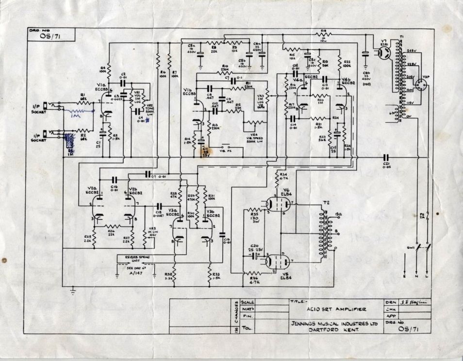
I was hoping one of you might have first-hand knowledge to help answer a question about the Vox AC-10 SRT amplifier. I'm in the process of building a clone of this amp, though I want to substitute a more conventional Fender-type reverb circuit. Unfortunately, the Vox schematic has some errors in it.
Can you help me understand what is *supposed* to happen with the 'dry' signal after it leaves V2a? Should most of it pass through the 470K resistor R29 to the grid of V4b?
Here's a link to the schematic:
http://i1295.photobucket.com/albums/b62 ... n5ubuv.jpg
I spoke with another builder, who was convinced that 100% of the dry signal should pass through the 22K resistor R26 that bridges the cathodes of V2. In his interpretation of the schematic, R29 would be connected between C7 and the grid of V4b.
Which is correct?
Vox AC-10 SRT circuit questions
Moderators: pompeiisneaks, Colossal
-
pompeiisneaks

- Site Admin
- Posts: 4222
- Joined: Sat Jan 14, 2017 4:36 pm
- Location: Washington State, USA
- Contact:
Re: Vox AC-10 SRT circuit questions
It seems oddly drawn, but i think it's correct. What i see, anyway, is that the signal out from V2a goes into ghe grid (pin2) of V3b, which outputs into the reverb pan. The reverb pan returns into the grid (pin7) of V3a and that is the reverb signal.
ALSO the signal follows up through the 100k and 470k resistors that tie in with the output of V2b into the PI. That part below of the 22k is probably sending the cathode signal into the cathode of V2b from V2a, as well, so some of that signal is blended with the output of the reverb, seems like multiple layers of blending going in, if I'm reading it right.
~Phil
tUber Nerd!
Re: Vox AC-10 SRT circuit questions
There are mistakes in the schematic. V3b and V4b grids are floating. I think R30 should go from V3b grid to ground and R29 should go from C16(V3b grid) to C7. R7 should go to V2b anode
Re: Vox AC-10 SRT circuit questions
This is how I interpreted the schematic:
However, another builder suggested this:
Thoughts???
However, another builder suggested this:
Thoughts???
You do not have the required permissions to view the files attached to this post.
Re: Vox AC-10 SRT circuit questions
I certainly would not use that schematic to build an amp. Look at V2B plate! 
Ah, I see you've spotted that error too.
Ah, I see you've spotted that error too.
-
pompeiisneaks
- Site Admin
- Posts: 4222
- Joined: Sat Jan 14, 2017 4:36 pm
- Location: Washington State, USA
- Contact:
Re: Vox AC-10 SRT circuit questions
I see those errors now, but was only looking at signal path, doh! yeah not sure, if that grid needs to be tied to earth via a 100k and the 470k was a mixer or not, that 100k may need to be there for the grid leak.
~Phil
~Phil
tUber Nerd!
Re: Vox AC-10 SRT circuit questions
Some of the details are a bit unimportant to me, since I will not be using the original Vox reverb circuit. But I will have to figure out whether the "dry" signal is supposed to flow through R29 (470K) on its way to V4. Also, I need to figure out how much of the "dry" signal is actually transferred from V2a to V2b via the 22K reistor that bridges the cathodes...
My plan had been to use a 12AT7 in place of V3, and use it to drive a reverb transformer /tank like fender. Then, I I was planning to use a 12DW7 in place of V2, which would allow me to use V2b as a 12AX7-type reverb recovery stage. However, I was NOT planning to connect the cathodes of V2 with a 22K resistor, thereby keeping the dry and wet signal paths completely separate... I wonder if this would would dramatically alter the 'dry' sound of the amp?
My plan had been to use a 12AT7 in place of V3, and use it to drive a reverb transformer /tank like fender. Then, I I was planning to use a 12DW7 in place of V2, which would allow me to use V2b as a 12AX7-type reverb recovery stage. However, I was NOT planning to connect the cathodes of V2 with a 22K resistor, thereby keeping the dry and wet signal paths completely separate... I wonder if this would would dramatically alter the 'dry' sound of the amp?
Re: Vox AC-10 SRT circuit questions
Look at the reverb circuit in this Magnatone amp. May shed some light on that Vox circuit. Page 4 breaks it down nicely...
http://sluckeyamps.com/magnatone/Magnatone_M10A.pdf
http://sluckeyamps.com/magnatone/Magnatone_M10A.pdf
Re: Vox AC-10 SRT circuit questions
Thanks for all the comments! From all my research, it seems likely that 100% of the dry signal passes through the 22K resistor that bridges the cathodes of V2. This changes my thinking on how best to modify the reverb circuit. I'm thinking that a 1-tube reverb circuit would make the most sense because no extra tubes would be required.
The circuit described here seems promising: https://el34world.com/Forum/index.php?topic=7957.0
The one concern I have about this is the output, which incorporates a 1M pot and 330K resistor in series.
If I understand the original Vox schematic correctly, it looks like the grid of V2b is grounded when the reverb is turned OFF. If I were to splice in the 1-tube reverb circuit from the above link, it looks like the grid of V2b would have a high impedance path to ground when the reverb is "OFF."
How will this affect the dry tone of the amp???
Re: Vox AC-10 SRT circuit questions
I'm struggling to reconcile the wiring in this original AC-10SRT with the schematic. It looks reversed from what I would have expected:
Typically, amp controls work so that turning a pot clockwise (viewed from the front) will increase the signal level. In this case, it looks to me that the resistance between the wet REVERB signal and GND would decrease as the pot turns clockwise, which should result in less reverb signal reaching the grid of V2b... What am I missing?!
Typically, amp controls work so that turning a pot clockwise (viewed from the front) will increase the signal level. In this case, it looks to me that the resistance between the wet REVERB signal and GND would decrease as the pot turns clockwise, which should result in less reverb signal reaching the grid of V2b... What am I missing?!
You do not have the required permissions to view the files attached to this post.
-
pompeiisneaks
- Site Admin
- Posts: 4222
- Joined: Sat Jan 14, 2017 4:36 pm
- Location: Washington State, USA
- Contact:
Re: Vox AC-10 SRT circuit questions
This is a different setup where at the far left rotation of the pot, for Volume that means resistance between pins 1 and 2 is at max and 2 and 3 is near 0, in this case the reverb signal is being shunted to ground so it want's low resistance to ground at 0 reverb, so all is dumped. As you roll right you're INcreasing resistance to ground so some of the reverb signal goes off to the signal path instead. If I'm understanding what I'm seeing there.
~Phil
~Phil
tUber Nerd!
Re: Vox AC-10 SRT circuit questions
What you describe is how I would expect it to work. Perhaps I'm confused about the pot functions internally...
With Pin 2 and Pin 3 tied to GND, wouldn't the resistance between Pin 1 and GND be at a *maximum* when the pot is turned to the left?!
With Pin 2 and Pin 3 tied to GND, wouldn't the resistance between Pin 1 and GND be at a *maximum* when the pot is turned to the left?!
-
pompeiisneaks
- Site Admin
- Posts: 4222
- Joined: Sat Jan 14, 2017 4:36 pm
- Location: Washington State, USA
- Contact:
Re: Vox AC-10 SRT circuit questions
Yes and no because the pin 1 is connected to pin 2 (wiper) and the reverb connecting is at pin 3, so it's resistance to ground is 0... This means the reverb signal goes straight to ground with zero resistance when the pot is at far left. As you raise the resistance between 1-2 (in this case that doesn't matter as wiper, 2, is tied to ground). Therefore the operating resistance that matters is between wiper (at earth potential) and the input of pin 3. So far left you are at ground far right you have full resistance between the 3rd pin and ground. Jumping the wiper and the 1 pin just ensure that if the wiper disconnects theres always resistance to earth via the input at 3.
Edit, had an error in text.
~Phil
Edit, had an error in text.
~Phil
tUber Nerd!
Re: Vox AC-10 SRT circuit questions
I figured it out... you are correct. In my mind, I had envisioned the resistive element inverted from how it actually is inside the pot. Mystery solved! Thanks!
-
pompeiisneaks
- Site Admin
- Posts: 4222
- Joined: Sat Jan 14, 2017 4:36 pm
- Location: Washington State, USA
- Contact:
Re: Vox AC-10 SRT circuit questions
No problem, I figured this stuff out by just connecting my dmm to the pins as I rotated it to get a sense of what was happening and the practical 'see it to believe it' worked but I'm glad it makes sense.
~Phil
~Phil
tUber Nerd!