Transformer Spacing & Orientation
Moderators: pompeiisneaks, Colossal

Transformer Spacing & Orientation
Being a newbie, I have been doing lots of reading on tube amp design. Well, one of the things I ran across talked about spacing the 2 trannies pretty good & mounting one of them at an angle to the other to reduce the flux field interference between them. This makes perfect sense to me, but when I look at the TW's or Marshalls or whatever, the trannies seem very close to each other and are oriented squarely.... Could using this spacing/orientation technique reduce some of the noises these amps are known for? And exactly how does the placement of the tubes and such come about? What determines the optimal positioning of the critical components? Is it guesswork, or is there a thought process involved? I ask because the chassis layout rarely looks symmetrical to me & I'm a sucker for balance.
Re: Transformer Spacing & Orientation
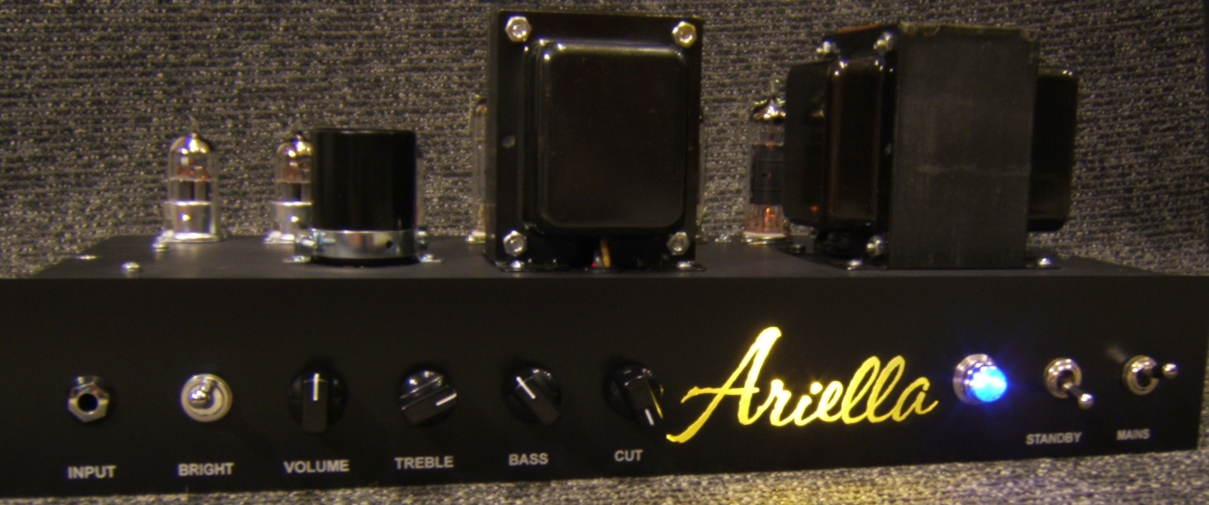
Distance between them is not all that important. What is important is to have the cores perpendicular. And, all the wreck layouts have the cores perpendicular. Now that you know they are indeed perpendicular, look at them again. 
http://paulrubyamplification.com/Ariella4.jpg
http://paulrubyamplification.com/Ariella4.jpg
Re: Transformer Spacing & Orientation
And answering your other questions....
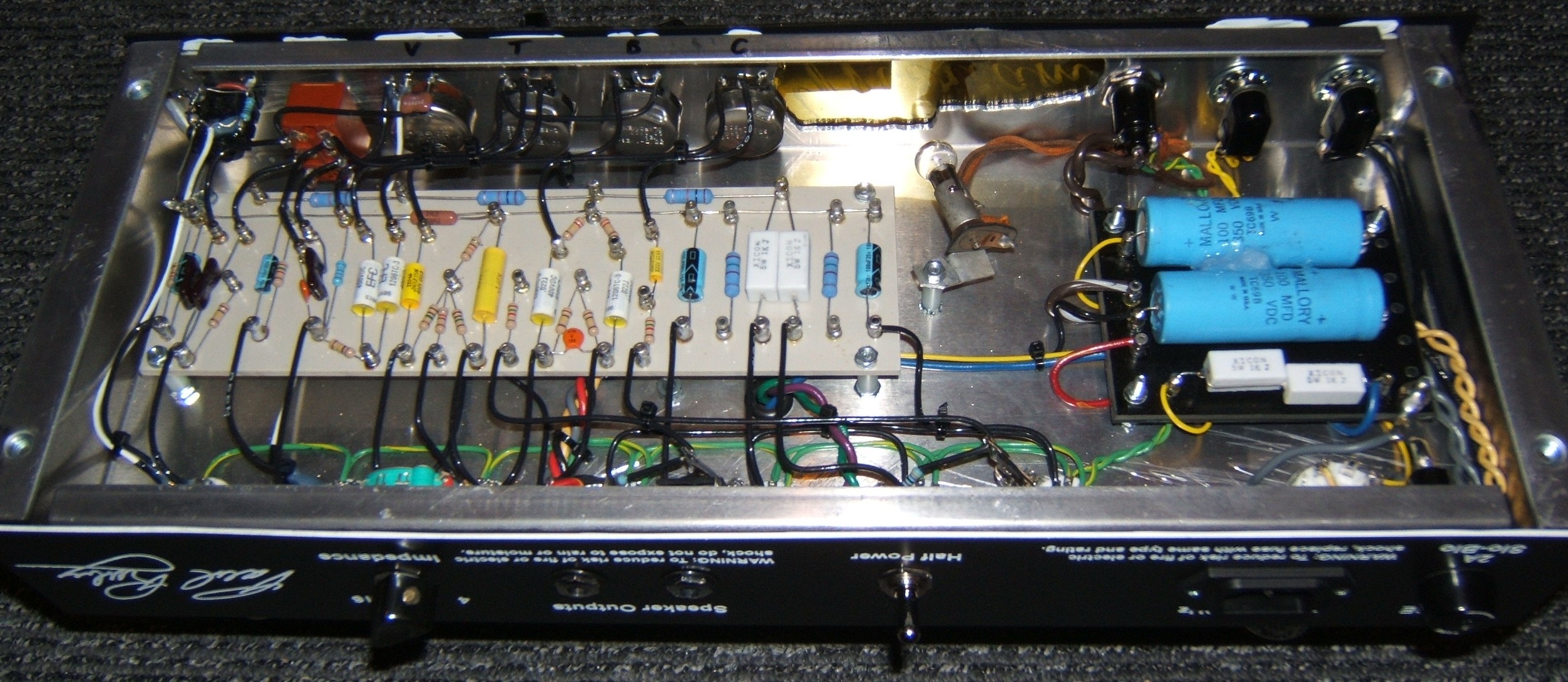
High voltage stuff goes to one far end of the chassis with the PT, recto and first filter cap (at minimum) all very close.
Input signal and initial gain stage goes all the way at the other end of the chassis (keep recto noise away from gain stages).
Signal amplification should happen in a linear order from one end of the chassis toward the other.
Run filament lines using twisted pair and keep them tight against the chassis.
Signal lines should fly up in the air away from the chassis perpendicular to the path of ground, B+ and filament lines.
Following the above results in a nice clean flow from one end toward the other.
http://paulrubyamplification.com/MiriamGuts4.jpg
Re: Transformer Spacing & Orientation
Old Hiwatt chassis had the PT at one end and the OT at the other, which made the amps nicely balanced to carry.  However, the chassis were large and deep, so they had plenty of space to play with internally.
[img:800:443]http://mhuss.com/Hiwatt/images/DR504_chassis.jpg[/img]
--mark
[img:800:443]http://mhuss.com/Hiwatt/images/DR504_chassis.jpg[/img]
--mark
Re: Transformer Spacing & Orientation
Hi Paul,paulruby wrote:And answering your other questions....
Signal amplification should happen in a linear order from one end of the chassis toward the other.
Run filament lines using twisted pair and keep them tight against the chassis.
Thanks for the info. You touched on a couple of other issues I was curious about. I noticed on the different gut shots of the TW clones that some had twisted wires coming off of the tube sockets & some didn't. I was wondering if these lines were meant to be differential pairs/twisted pairs, because if they are, then the wires have to be the same length as well as twisted to cancel each other out. Sorry, I'm a PCB designer by trade, so I think about these things a little different. On a PCB these traces would be equal line length and run side by side so they could couple into each other. Thanks for pointing out that these are indeed twisted pairs.
Another point you brought up is about the signal path through the circuitry. When I lay out a circuit or a board, I make sure the signal paths are as smooth as possible and that they don't change direction too much going through the comps. This reduces reflection and just makes a healthier signal. Anyway, I noticed on the TW that there are resistor networks that have the signal snaking back and forth instead of going in a straight line, which kinda bugs me. But I work in a mixed signal high speed environment, so these are probably irrelevant points in regards to the TWs.
Thanks again for the info. I checked out your site & you have some really sweet designs there. Nice work!
~Tim
Re: Transformer Spacing & Orientation
Hi Mark,mhuss wrote:Old Hiwatt chassis had the PT at one end and the OT at the other, which made the amps nicely balanced to carry.
--mark
Thanks for the Hiwatt pic. That helps answer my question about placement. I have on old 70s Hiwatt Custom 100, but haven't autopsied it yet. I know that Dave made these gems really different than what was out at the time. I love mine. It has the biggest clean sound there is. I used it for part of my bass rig in the 80s. I played a Rickenbacker 4001 stereo through an Orange 120 / two 4X12 cabs for the high end (treble pickup) & the neck pickup went through the Hiwatt 100 and two 1X18 cabs with EV speakers. It smoked! Great Chris Squire/Geddy Lee sound. I miss those days!
Re: Transformer Spacing & Orientation
Sweet!! That must've sounded awesome, but been a pain in the back to cart around.juse wrote: ...I played a Rickenbacker 4001 stereo through an Orange 120 / two 4X12 cabs for the high end (treble pickup) & the neck pickup went through the Hiwatt 100 and two 1X18 cabs with EV speakers.
--mark
Re: Transformer Spacing & Orientation
It was a pain, but back then bigger was better & I was pretty young and healthy. I lugged it all around for years & just recently got rid of the two 1X18 cabs. I can't seem to part with the rest of it, so it is stashed in my garage. These days I play guitar & have a Vox combo as well as a 2X12 cab with wheels..... lots easier on the ole' back! The Orange honks through that 2X12. I can't wait to make my Express clone, though. I envy all you guys that already have one.
Re: Transformer Spacing & Orientation
All valid concerns once you get into the MHz range. But, no issue at all for audio.juse wrote:Hi Paul,paulruby wrote:And answering your other questions....
Signal amplification should happen in a linear order from one end of the chassis toward the other.
Run filament lines using twisted pair and keep them tight against the chassis.
Thanks for the info. You touched on a couple of other issues I was curious about. I noticed on the different gut shots of the TW clones that some had twisted wires coming off of the tube sockets & some didn't. I was wondering if these lines were meant to be differential pairs/twisted pairs, because if they are, then the wires have to be the same length as well as twisted to cancel each other out. Sorry, I'm a PCB designer by trade, so I think about these things a little different. On a PCB these traces would be equal line length and run side by side so they could couple into each other. Thanks for pointing out that these are indeed twisted pairs.
Another point you brought up is about the signal path through the circuitry. When I lay out a circuit or a board, I make sure the signal paths are as smooth as possible and that they don't change direction too much going through the comps. This reduces reflection and just makes a healthier signal. Anyway, I noticed on the TW that there are resistor networks that have the signal snaking back and forth instead of going in a straight line, which kinda bugs me. But I work in a mixed signal high speed environment, so these are probably irrelevant points in regards to the TWs.
Thanks again for the info. I checked out your site & you have some really sweet designs there. Nice work!
~Tim