Search found 205 matches
- Fri Nov 13, 2020 2:13 pm
- Forum: Garage Talk
- Topic: How do you organize your component supply?
- Replies: 8
- Views: 1452
Re: How do you organize your component supply?
I'd like a better way to organize and store my components: resistors, caps, switches, diodes, etc. I started by re-using a kit organizer, but I don't care for how most plastic organizers have non-ideal dimensions, and seem to require that you bend leads to make components fit. I have a decent amoun...
- Sat Nov 07, 2020 6:57 pm
- Forum: Technical Discussion
- Topic: Elevated heater worry: loads circuit
- Replies: 14
- Views: 930
Re: Elevated heater worry: loads circuit
+1, have done exactly this on a couple builds, albeit with a 500K/100K divider. No problems whatsoever.martin manning wrote: ↑Sat Nov 07, 2020 2:43 pm Put the divider on the screen node. That additional 1 mA will never be missed.
- Sat Nov 07, 2020 6:26 pm
- Forum: Technical Discussion
- Topic: 2020 Monkeymatic Lassen #4 (1482)
- Replies: 40
- Views: 2497
Re: 2020 Monkeymatic Lassen #4 (1482)
Very cool!
Is this the first project with the socket PCBs? What do you think of them?
Is this the first project with the socket PCBs? What do you think of them?
- Fri Nov 06, 2020 3:26 pm
- Forum: Technical Discussion
- Topic: Choke for soldano build, and some other questions.
- Replies: 12
- Views: 875
Re: Choke for soldano build, and some other questions.
Yeah pretty sure that recovery stage after the effects loop is wrong on the schematic.
Anyway the build is working now, here's a pic!
EDIT: Audio sample for the interested!
Anyway the build is working now, here's a pic!
EDIT: Audio sample for the interested!
- Thu Nov 05, 2020 11:05 pm
- Forum: Technical Discussion
- Topic: Choke for soldano build, and some other questions.
- Replies: 12
- Views: 875
Re: Choke for soldano build, and some other questions.
Hold up, is the DCCF coming out of the effects loop wrong on the schematic? Soldano_super_lead_60.pdf Is it possible to input to the cathode like this? I'm looking at other schematics, surely the 1K should be the cathode resistor on the first stage, 1M grid leak, and the 100K plate resistor on the f...
- Tue Nov 03, 2020 6:06 pm
- Forum: Technical Discussion
- Topic: Benson Monarch
- Replies: 480
- Views: 75390
- Mon Nov 02, 2020 1:50 pm
- Forum: Technical Discussion
- Topic: Benson Monarch
- Replies: 480
- Views: 75390
Re: Benson Monarch
+1 for seeing the schematic, I wanna see what the hype is all about.
Going out on a limb and guessing it probably some resistors and capacitors. Maybe a potentiometer or two.
Going out on a limb and guessing it probably some resistors and capacitors. Maybe a potentiometer or two.
- Tue Oct 27, 2020 12:53 am
- Forum: Technical Discussion
- Topic: Current draw in primary of unloaded PT?
- Replies: 9
- Views: 446
Re: Current draw in primary of unloaded PT?
the yba-1 i had called for way cooler bias than i would've liked on the factory schematic so that's very likely. i added 1 ohm resistors between pins 1 and 8 (one per pair would work in your case) obviously have to rewire what goes to ground but that and the tube bias calc on robinette's site make ...
- Mon Oct 26, 2020 11:56 pm
- Forum: Technical Discussion
- Topic: port city pearl
- Replies: 1
- Views: 302
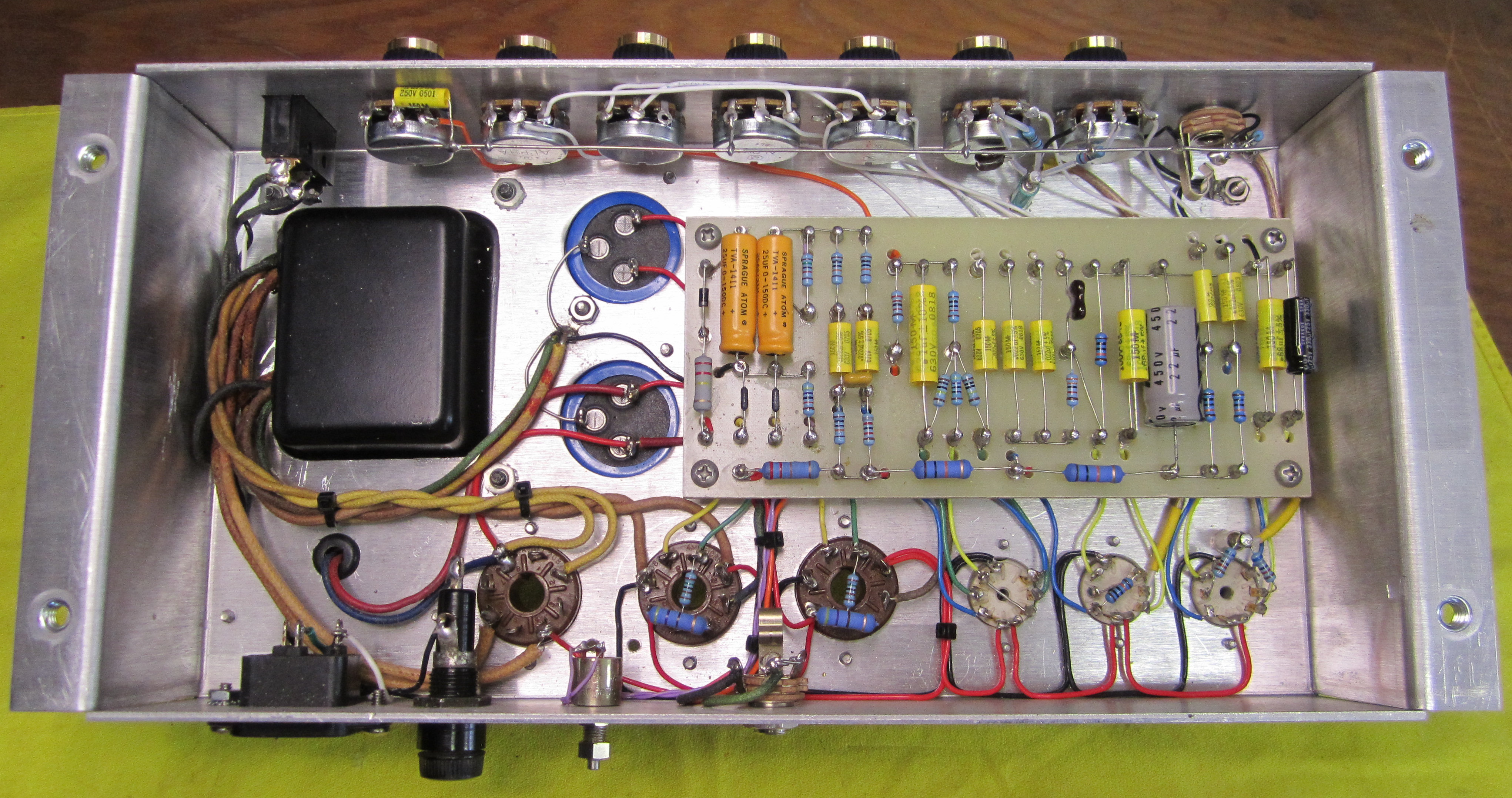
Re: port city pearl
I had one briefly, pretty Fender-ish.
Gain stage - fender TMB - gain stage.
DCCF driven effects loop, returns straight into long tail PI.
~460V on the plates.
Gain stage - fender TMB - gain stage.
DCCF driven effects loop, returns straight into long tail PI.
~460V on the plates.
- Mon Oct 26, 2020 11:31 pm
- Forum: Technical Discussion
- Topic: Current draw in primary of unloaded PT?
- Replies: 9
- Views: 446
Re: Current draw in primary of unloaded PT?
If there was an actual PT fault such as shorted turns, the PT would be drawing very high current, and blow the fuse. That's what I was thinking too. I did fully fire it up, drawing about 1.4A at 118V, with ~5V on the screen dropper resistor. Side note, how does the biasing procedure work? It states...
- Sun Oct 25, 2020 8:34 pm
- Forum: Technical Discussion
- Topic: Current draw in primary of unloaded PT?
- Replies: 9
- Views: 446
Re: Current draw in primary of unloaded PT?
I commonly see 7-15 watts drawn by unloaded PTs of various sizes. So your 0.8A draw is not outside the norm. Gotcha, it's a bit less, 0.66mA, but I hear you. Just to be 100% sure, I disconnected all the secondary taps, thinking maybe something wrong with the standby switch, or filament winding. No ...
- Sun Oct 25, 2020 7:27 pm
- Forum: Technical Discussion
- Topic: The new cat
- Replies: 13
- Views: 1109
Re: The new cat
Build looks great! Very clean
- Sun Oct 25, 2020 5:09 pm
- Forum: Technical Discussion
- Topic: Current draw in primary of unloaded PT?
- Replies: 9
- Views: 446
Re: Current draw in primary of unloaded PT?
The tube filaments is a considerable current draw. Just the 4 EL34s present a 37 watt load on the PT. That would be .3A @120V in the primary even if the PT was perfect and had no losses. I'm not even gonna add in the other six tubes. So, the filaments of just the EL34s account for almost half of th...
- Sun Oct 25, 2020 3:29 pm
- Forum: Technical Discussion
- Topic: Current draw in primary of unloaded PT?
- Replies: 9
- Views: 446
Current draw in primary of unloaded PT?
Just picked up a ~74 Traynor YGL-3A. Album. Schematic. I've completed the work I wanted, mostly just replacing e.caps. I also modded the bias supply to be a bit safer (adjustment pot is now a variable resistor, rather than the bias being supplied from the wiper) I was forming up the new caps, and no...
- Wed Oct 14, 2020 10:05 pm
- Forum: Technical Discussion
- Topic: Choke for soldano build, and some other questions.
- Replies: 12
- Views: 875
Re: Choke for soldano build, and some other questions.
Alright cool, I'll give the 1 turn pot a try.sluckey wrote: ↑Wed Oct 14, 2020 9:12 pm A 10 turn pot would be more precise but I've never had any difficulty setting bias accurately with a 50K pot. I've used this pot on several builds...
http://sluckeyamps.com/6v6plexi/P-6V6_05_big.jpg